Comparison Between Reproducibility of 3D Point Manual Identification on Volume Rendering Based on Isosurface and Multiplaner Reconstruction Acquired From CBCT- Juniper Publishers
Juniper Publishers- Open Access Journal of Dentistry & Oral Health
Comparison Between Reproducibility of 3D Point Manual Identification on Volume Rendering Based on Isosurface and Multiplaner Reconstruction Acquired From CBCT- Juniper Publishers
Authored by Ayman R Khalifa
Introduction
Through the past, century radiographs has been used in medicine as one of the most valuable diagnostic aid providing informations about craniofacial anatomy including special lateral cephalometric view used since the early 30 of the 1900 in research work for treatment evaluation pre and post operative, individual patients vary from population norms, forecastingand following growth and treatment changes, and establishing descriptive communications [1] between clinicians but we forgot other views which is a big mistake to assess 3D craniofacial structure with 2D view suffer from errors in projection and superimposition [2,3] imagingartifacts, variations in magnification, head position errors and limitation of information but due to technology limitation.
At begin of this century recent 3D technology raised from computed tomography (CT), magnetic resonance imaging (MRI) machines and recently developed cone beam computed tomography (CBCT) with low radiation dose and more rapid imaging to make full 3-dimenstional (3D) diagnosis by 3D rendering,maximum intensity projection (MIP) [4] and multiplaner reconstruction (MPR) [5] or virtual x-ray machine producing desired 2D view from one 3D radiograph with uses ranging from diagnosis and treatment planning of congenital malformations, to localization of impacted teeth, to positioning of dental in plants.
As a normal development, 3D technology, has changed from viewing of 3D reconstructed volume to a simple volumetric measurement then trials to construct a reliable cephalometric analysis but still not fully established.
There are many means of viewing reconstructed CBCT in 3D display as volume rendering based on iso surface and Multiplaner reconstruction (MPR).
Volume rendering [6], volumes are 3D data, usually acquired from computed tomography or MRI scans volume rendering shows the whole volume as a solid object as images are composed of pixels, so are volumes composed of voxels. Each voxel can have a density value, which usually ranges from 0 to 255. The density of a vessel is related to the density of the tissue at the voxel’s location Isosurface.
An isosurfaces [7] iso (also known as level sets, implicit surfaces, varieties, membranes, or contours) of 3D scalar-valued data at interactive rates, allowing a user to browse the data by adjusting the iso value. iso-value or threshold is specified from the Histogram window. View box supports two iso-values and can show two isosurfaces, the Primary (soft tissue) and the Secondary (hard tissue).
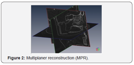
Multiplaner Reconstruction (MPR)
It is viewing of reconstructed volume as X, Y, and Z slices called in view box ortho slices you can make 2D slicing in any spatial direction.
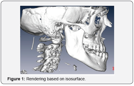
In This article we will evaluate Reproducibility of points in two 3D views direct volume rendering based on isosurface and multiplaner reconstruction as a base for new 3Dcephalometric design (Figure 1 & 2).
Material and Method
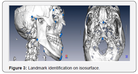
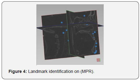
From 4 patients 9CBCT scans by random x-ray intensity and time of imaging with slices dimension 618x618 , 0.3-mm thickness, bit-depth 16, and resolution 88 dpi were obtained by ilumact machine and exported in digital imaging communication of medicine (DICOM ) format, Data were imported in viewbox version 4.0.0.101 for experimental use only 2D slices were assembled in 3D volume by reconstruction, rendering based on isosurfaces was performed for the soft and hard tissues by manipulation of the histogram to limit the data that are displayed. Filter was made to reduce noise without reducing actual soft tissue or osseous anatomy, also reslicing in three X, Y, and Zaxis was done after orientation guided by Frankfort Horizontal plan (Figure 3 & 4).
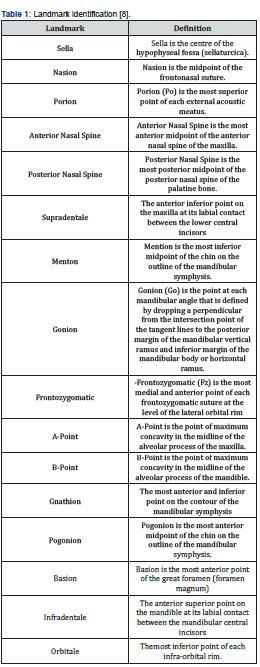
Landmark Identification [3] (Table 1)
Digitization
Direct manual points identification of twenty landmarks was done on rendered isosurface some tools as transparency and clipping were used to help in digitization and show internal structure as it appears as solid 3D object but in MPR points were checked on the three slices directions in the same time.
Three observers with different scientific degrees participated in this study, before the viewing sessions, each observer received training on 3Dlandmark identification included in this study on two viewing methods.Observation sessions for each observer on each viewing method were taken over 2 weeks. After the observers digitized all landmarks, the landmark coordinates in mm were exported into Excel (Microsoft) and saved for subsequent assessment of precision.
Results
Statistics and results analysis
Both Standard deviation (SD) for each coordinate X, Y, Z and (SD) of direct distant in mm between three session were calculated to show error of each coordinate component of each point and whole error in mm intra and inter observer in each method and between the two methods themselves.
Some points are expired totally as gonionand some points expired inisosurface as Sella has high error in isosurfacethan MPR due to difficulty to locate in 3D cavity, generally error in MPR is higher than isosurfacealthough MPR is accurate by logic but working 2D on 3D object and head orientation may be the cause of that, some coordinate is accurate to use in measurements as z in Nasion, ANS, Orbitale, Porion, Basion, PNS, Menton, Infra and Supra dentale, Y in B, A, ANS, Nasion, Infra and Supra dentale, X ANS, PNS and Porion.
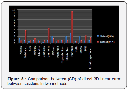
- Generally Landmark identification on MPR has higher error than isosurface rendering especially in points Orbital, Gonion and Porion (Figure 5).
- Comparison between (SD) of direct 3D linear error between sessions in two methods.
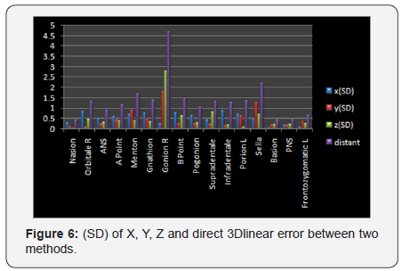
- To check comparability of results from two methods we found that there is high difference in Orbital, Gonion, Porion, A and Sella between two viewing methods. (SD) of X, Y, Z and direct 3Dlinear error between two methods (Figure 6).
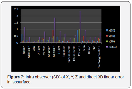
- Intra observer error in isosurface increases in Nasion, Gonion and porion points. Intra observer (SD) of X, Y, Z and direct 3D linear error in isosurface (Figure 7).
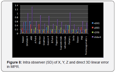
- Intra observer error in MPR increases in Orbital, ANS, Menton, Gonion and Porion points. Intra observer (SD) of X, Y, Z and direct 3D linear error in MPR (Figure 8).
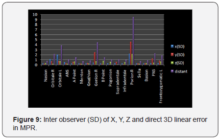
- Inter observer error in MPRis high but increases most in Orbital, Gonion, Porion and PNS points. Inter observer (SD) of X, Y, Z and direct 3D linear error in MPR (Figure 9).
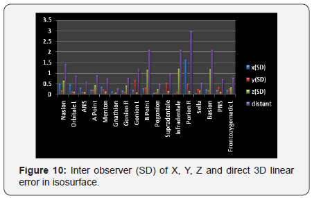
- Inter observer error in isosurface increases in B, Porion and Basion points. Inter observer (SD) of X, Y, Z and direct 3D linear error in isosurface (Figure 10).
Discussion
It was found that error increases in points located on wide flat or widely curved anatomical landmarks , Bad quality CBCT and non standard head position affect results too, The difference between MPR and isosurface because of MPR shows raw data without computer processingand in MPR location of hard and soft tissues depends on observer judgment only while in isosurface rendering depend on histogram either automatic or manually defined according to CBCT this means that main fountainof error of rendering is indefinite differentiation between radio densities around isovalue or threshold because observer will not see any radio density lower than defined value in secondary isosurface rendering but MPR you will see all data,Demetrious1 worked on solving this problem by gradient (relation of voxel with others) MPR depends completely on observer while isosurface have computer factor so in MPR observers totally depend on their experience so they must have powerful 3D imagination during working on 2D slices, points on sharp anatomical structures appear very sharp but points on wide arias aremuch more difficult to locate while isosurface needs less experience.
By evaluation of current results this shows that error in isosurface comes from error in rendering technique and poor land mark identification, As landmark identification in 2Dwas by evaluation of x andycoordinate but in 3Dobserver evaluate 3 coordinatex, y and zthis increased error possibility also view shown in 3D differs much than 2D structure that was satisfactory identified as Nasion in radiolucency representing suture between frontal and nasal bones now in 3D has new ingredient you must evaluate position on the suture in right left direction there is no suture superimposition to itself that was signifying landmark just line on wide surface this affects traditional measurement depending on Na vertical.
Basion was sharply located but now has wide area to place, many points depend on standardization of head position as Orbitale, Porion, Mentonand Pogonion now we cannot say that they can be locatedby standard method due to absence of cephalostate or cephalostate like tool, error of rendering can be avoided by multiplaner reconstruction but this method needs very high experience and needsextensive training,cephalometric reliable analysis must be based onuser friendly method of landmark identification this is impossible by current ways jailed by 2D minds, error in MPR comes from non standard head position makes illusion in slicing direction we can imagine Orbitale identification if we moved by axial slicing until we see most inferior point as last point of bone meeting each other this point will be changed by direction of slicing and so all points depend on head orientation, Points on wide areas as Gonion sharp identification has become impossible,Menton also is located on wide area but has another problem it should be located in mid line but mid line should be standardalso anteroposterior location is questionable.
Observerangel of vision affectsall points identification and affectsaccuracywe have learned this in school anyone wants to make measurement should look perpendicular on line he wants to measure otherwise error will appear depending on viewing angel and so virtual skull model imitating real skull in real world there will be error by angel of vision in landmark identification and so based on measurement so head orientation is essential for reproducible 3Dlandmark identification
Conclusion
Landmark identification on MPR has higher error than isosurface rendering. Results derived from two methods are not comparable because of general difference between results.
For more Open Access Journals in Juniper Publishers please click on: https://juniperpublishers.com


Comments
Post a Comment